Parsing textual input with IncQuery

Parsing textual notation has a long history in computer science. This long time has produced many great and efficient parsing algorithms, which were optimized to the extreme by compilers for different programming languages. However in the recent years the development of integrated development environments are accelerated, adding more and more services to previously simple features like code editors and automatic background compilation. These with the rise of domain specific language frameworks which allows the user to define an arbitrary language declaratively causes that present-day computers still struggle under the resource requirements of these technologies.

While waiting in front of a textual editor, I’ve started thinking about why does the editor need to re-run the parsing algorithm every time I hit button (of course I’m aware of the fact that the main cause of the slow responsibility is probably not the parsing algorithm itself). A fully incremental approach could make these tools more responsive which would remove a lot of pain from its users. As I’m already familiar with an incremental query engine (IncQuery) the thought about using it to parse text couldn’t leave my mind.

The following article presents the experiment I’ve done as a proof-of-concept. It’s far from being useful and reveals more problems than it solves it does not produce an AST just accepts or rejects the input string, however it may be interesting as an approach and maybe in the future it will be more than just a stupid idea. Continue reading “Parsing textual input with IncQuery”

Yet another textual modeling framework

Most of the time I try to avoid reinventing the wheel. And most of the time I fail and forced to do so. That’s what happened to me when I decided to write my own textual modeling framework. I’ve used (and currently using) Xtext in several projects and tried EMFText once. Both of them are great projects with great possibilities, but I’ve come across a problem which required a different approach. I needed a more dynamic toolkit, where the language is extensible and easier to maintain. Continue reading “Yet another textual modeling framework”

DIY musical doorbell

A doorbell is not the most important equipment of a home, however it is necessary and it still matters in a way. It is the thing that makes the first impression of your home to any visitor. The standard school-bell type doorbells hurts the ears and freaks out everyone who dares to touch the button and anyone who is unfortunate to be home at the time. A musical doorbell can be really expensive and the sound of the cheaper ones are simply annoying. Why not try to build one at home?

Hardware

It can be easier than it seems at first glance. Almost every part of it can be found in the drawer of an average hardware hacker:

  • Any speaker scooped from an old PC
  • A cheap MCU
  • An NPN transistor
  • An 1K resistor
  • Optionally a potmeter for volume control
  • 4 diodes
  • 2 capacitors
  • An 5V linear regulator (L7805)

The theory of operation is really simple: the MCU drives the speaker with a square wave on an arbitrary frequency to make a sound. Because the MCU usually cannot bear high current enough to make it loud, a transistor is used to drive the speaker.

The power source may be a standard bell transformer, which makes 12V AC from the 230V AC. In my case it was given as in our apartment building there is one generator for more apartments. To provide a stable 5V for the MCU, a simple Graetz-bridge can be used along with a linear regulator.

Doorbell schematic (https://www.circuitlab.com/circuit/3x9m3u/doorbell/)

Software

The software part is just as simple. The first problem is to make the proper frequency for the square wave output. The simplest approach for this is to use a timer integrated into the MCU, and toggle the output on the timer interrupt. Now the frequency can be set by the timer options.

The other task of the MCU to switch the settings of the mentioned timer after a time to make a series of sounds. I’ve used another timer to interrupt in every ~0.2sec, which decrements a counter to determine the delay for the sound. If the counter reaches zero, the new timer settings and delay counter are loaded from the program memory tables.

Calculation of timer settings

The music you want the bell to play, is a series of sounds with determined frequency. This must be converted to a series of timer settings. For the PIC16F1824 I’ve used, this settings includes the compare register value along with the pre- and postscaler settings. To determine the best settings for each sound frequency (best = real frequency closest to nominal within the available set of register values) is a straightforward task, but requires a lot of calculations. It is much easier to write a script that makes all the calculations and generates the proper code tables for the program. This way it is easy to change the music to whatever you want.

Finish the bell

All is left is a bit of soldering and putting it in a suitable box:

https://i0.wp.com/lh5.googleusercontent.com/-bCo7Z1mv3Jo/UBps6axVuLI/AAAAAAAAL00/Du4SNKyLdjg/s640/IMG_1373_cut.JPG?resize=512%2C450&ssl=1
The finished doorbell

References

Reusing PDE in modeling context

If you’re developing with EMF it is a common task to separate the model into multiple files along with enabling the user to create crosslinks between them. This works out-of box if the files are located inside the same project. However, in some cases for larger models it is simply not enough. It can be useful to be able to define reusable (and versioned) packets of models and enable the user to define a configuration which determines the imported model packages. Sounds familiar? The same functionality exists in PDE. Maybe it can be reused for non-java purposes.

Continue reading “Reusing PDE in modeling context”

How to turn a printer power unit to a fancy lab power supply

A dead printer is a great possibility to gain useful components. You can scoop many kind of parts, like DC motors (stepper motors if you’re lucky), wires, gears, etc.. And of course a power supply unit. The power supply can be useful in many ways, for example as a lab power supply. But without a case it is a bit dangerous, as you can accidentally touch something, which would be painful. Warning! Don’t try this at home, unless you’re perfectly know what are you doing, and have practice handling with 220 Volts.

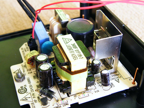
Now, if you dare, run up to attic, and bring down the dead printer, clean the dust and grab a screwdriver. After tearing down the device to the smallest parts possible without breaking anything, you should see a component like this:

DSCF7533

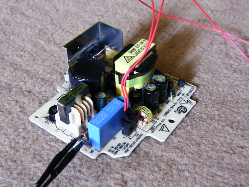
It’s rather simple: it has an input, AC 220 Volts in Europe usually connected with thick wires. The output varies by brand and type but it’s surely DC, low voltage connected with thin wires. Look for the numbers printed on the board, they usually tell the output voltage and maximum power. In this case, it’s 18 Volts and 25 Watts. This is more than enough for experimental purposes.

Before you continue, check it out carefully. The printer is not working because of a cause, and maybe that cause is the power supply itself. The easiest way to check is to connect a multimeter to the output and plug it in. Be very careful with this step, try to not touch the device while it is under power.

If the power supply is not working, try to check out the fuse. If it’s burnt, you should replace it and try again. If it solves the problem, then maybe it was the cause that rendered the printer dead. At this point you can just put the printer together, and live on. And of course make merit of fixing a dead printer. Both cases, continue reading, the lab supply is far from finished yet.

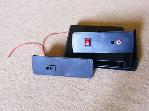
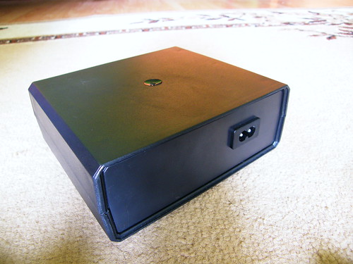
To make it safe and easy to use, it should be inserted in a case. You can buy one in any electronics shop. I’ve used a plastic one as it’s easier to use, but many thinks that a metal box looks better. If you use a metal box, more work is needed as you should take care of grounding the box itself, and insulation of the power supply board. A printer is usually not grounded, so the power cable of the printer won’t be adequate. I’ve reused the AC connector of the printer, it can be clipped easily into a matching hole, which was easy to cut into the back board of the box using a drill and a rasper:

DSCF7537

I’ve used similar method on the front board, which contains two banana connectors for the output, and a switch which enables to turn off the device without unplugging it:

DSCF7536

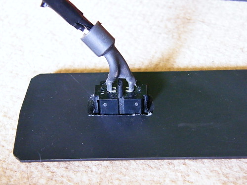
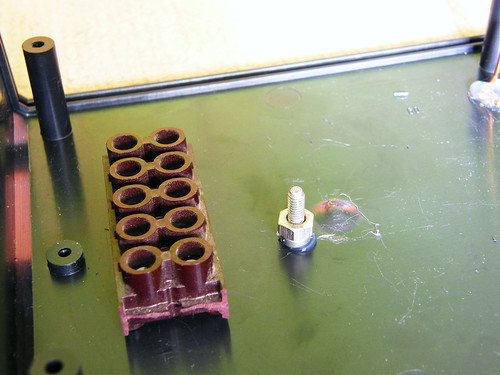
Soldering is hard in small places, and the hot iron can damage the plastic box badly. So instead of soldering the wires together in the box, I recommend using a terminal block as I did. The block can be fixed to the box using a glue gun. I’ve also used glue gun to mount a screw and two copper wires into the hold the power supply board in place:

DSCF7540

DSCF7543

The hard work is done, all is left is to put the whole thing together. Doing some wiring work:

DSCF7546

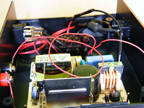
And then voilá, it’s finished:

DSCF7548

DSCF7549

Have fun doing your own lab power supply! More pictures here:http://www.flickr.com/photos/gbalage/sets/72157624262231051/